Switchboard Asset Tracker Installation Guide
Last updated September 11, 2024
Note: This feature is only available for companies that have the Switchboard Asset Tracking & Cloud Platform feature enabled. To learn more, go here: Switchboard Asset Tracking & Cloud Platform
The installation of the Switchboard Asset Tracker and its antennas can have a major impact on the Switchboard Asset Tracker’s performance. It is recommended that installers be familiar with the installation of GPS and cellular devices and are comfortable in a vehicle environment.
PLANNING THE INSTALLATION
Verify Power, Ground and Ignition
Be sure to check each source (power, ground and ignition) to ensure that the proper signaling exists. This is typically accomplished with a multi-meter.
Before drilling any holes or running any wires, decide where each hardware component will be located (Switchboard Asset Tracker, antennas, peripherals, etc.). Be sure that the cables to the Switchboard Asset Tracker are not bent or constricted in any way. Also make sure that the Switchboard Asset Tracker is kept free from direct exposure to the elements (sun, heat, rain, moisture etc...).
Be advised that an installation that violates the environmental specifications of the Switchboard Asset Tracker will void the warranty.
The best way to ensure a trouble-free installation is to consider your options and make some decisions before you start. Take a look at the vehicle and determine how to best install the Switchboard Asset Tracker for the following purposes:
- Accurate data gathering and simulation of how customers actually use your solution
- Ongoing monitoring and maintenance of Switchboard Asset Tracker equipment
- Accidental or intentional alteration of the equipment or cable connections
The following sections cover some of the issues to consider when planning your Switchboard Asset Tracker installation.
Size and Placement of Switchboard Asset Tracker Unit
The dimensions of the Switchboard Asset Tracker should be taken into account, particularly when installing in a vehicle:
Whether you intend to place the Switchboard Asset Tracker under a seat or into a cavity behind the vehicle’s interior molded trim, be sure the Switchboard Asset Tracker will fit before drilling any holes or running cable
- Be certain that the cables running to the Switchboard Asset Tracker will not be bent or constricted. Damage to the cables may impede the Switchboard Asset Tracker’s performance.
- Be certain that the installation point will not violate any of the Switchboard Asset Tracker’s environmental specification (temperature, moisture, etc…) as improper installation of the Switchboard Asset Tracker may void the warranty.
Typical installations will place the Switchboard Asset Tracker under the vehicle dash board, or in the trunk. Make sure you can get access to the unit afterwards as under some circumstances it may be necessary to add additional wiring or connections to the Switchboard Asset Tracker.
Placement of Antennas
There are effectively three options for placements of an antenna:
- Roof-mount (magnetic or thru-hole)
- Glass-mount
- Covert (e.g. under the seat, dash, etc…)
Comm Antenna Placement Guidelines
The Comm. Antenna must be located at least 20cm away from vehicle passengers, other personnel, or bystanders in order to comply with FCC radio frequency exposure limits.
Typically, the Comm antenna used by the Switchboard Asset Tracker for wireless service is a standard 3-dB gain whip. It mounts with standard mounts (i.e. thru-hole, magnetic mount or peel and stick) and requires a ground plane to work properly. If possible, it should be located at least 3 feet from the GPS antenna. Ensure that the cable does not get crushed during installation.
Please note that the antennas provided combine both the GPS and Comm portions.
GPS Antenna Placement Guidelines
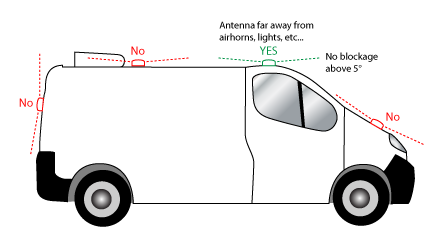
In order to maximize the performance of the Switchboard Asset Tracker the GPS antenna should have a clear view of the sky. When installing the GPS antenna on a vehicle, make sure that there are no obstructions close to the antenna that might block the view 360° to the horizon. Things like air horns, lights, vents, etc… should not block the antenna beyond 5° above the horizon. The best location is usually near the center of the roof; however it is also desirable to locate the cellular antenna as far from the GPS antenna as is practical.
Examples of good and poor GPS antenna placements
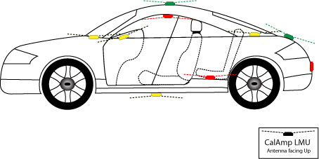
The received signal levels at the GPS antenna from the satellites are very low in power (approximately -136 dBm), so any blockage of the antenna can affect the quality of the location computed by the receiver. Kinks or tight knots in the antenna cable can also prevent the GPS receiver from operating properly. When laying out the antenna cable, care should be taken so that the cable is not subjected to crushing or strain.
Examples of Good (Green), OK(Yellow) and Poor(Red) combo antenna placements
Protection from Heat
It is best not to place the Switchboard Asset Tracker unit in an unusually warm location such as directly near heater vents, near hot engine components or in direct sunlight. The maximum temperature that can be tolerated by the Switchboard Asset Tracker is described.
Cable Length
The RF cables which are provided for connecting to the Switchboard Asset Tracker antennas should be used at the length provided. Do not cut cables. Instead, coil any excess cable length, making sure not to crimp or flatten the antenna cable.
GENERAL WIRING INSTRUCTIONS
The following instructions address trailer installations and are applicable to other types of non-motorized equipment.
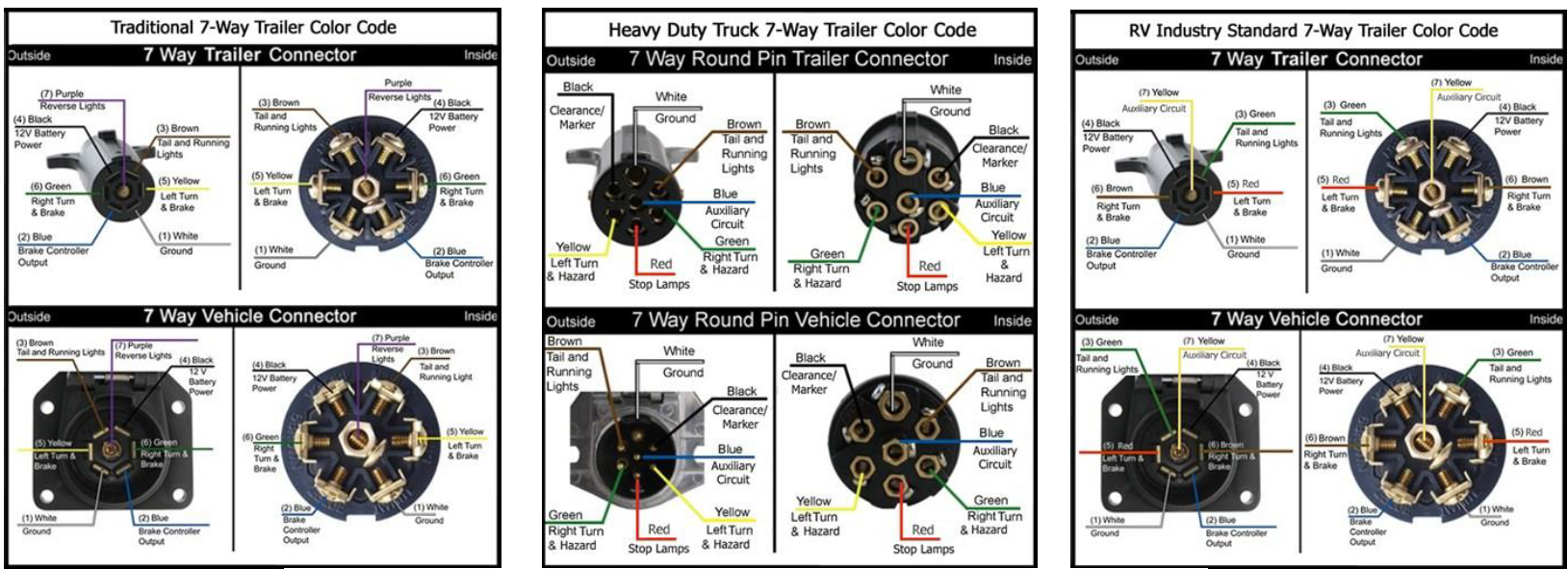
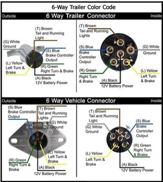
Locate the power input line from the connector used to attach trailer to the tractor/truck. Typically, the center pin will be switched 12v power.
- It is acceptable to wire the device in parallel with other equipment on the trailer (e.g., lights, lamps, etc.) because an internal diode will prevent the battery from draining through the auxiliary equipment while not in use.
- Use a 6-Way connector for the basic lighting functions (e.g., power, turn and brake). The ground and two extra pins are available to provide two additional functions. The round connectors are common on horse trailers and square connectors are commonly used with campers.
- In addition to the basic lighting functions, the 7-way connectors have additional pins for electric brakes, a 12 volt "hot" lead and backup lights. The flat pin connector is common on newer trucks and SUVs.
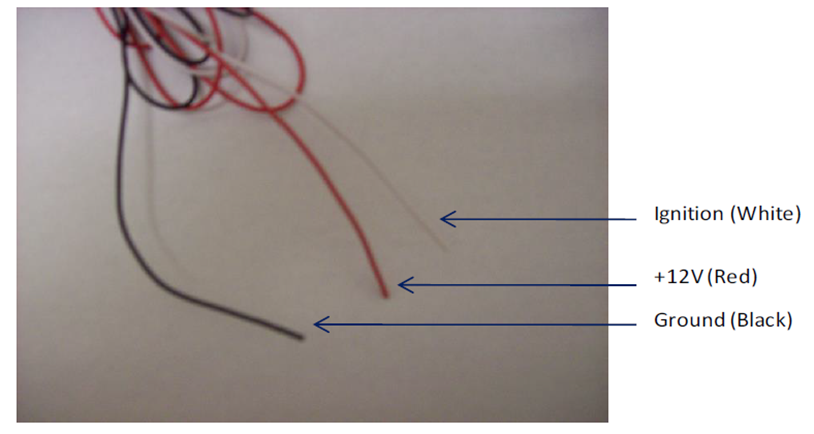
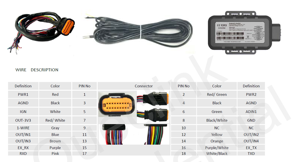
Combine both the red power wire and the white ignition wire to the trailer’s 12v battery power wire.
The ground line (black wire) must be connected to chassis ground and secured with a factory bolt or screw insuring wire to metal connection.
Place the Switchboard Asset Tracker unit in the vehicle.
Typically, the Switchboard Asset Tracker should be placed under the passenger seat or dashboard of the vehicle. Switchboard Asset Trackers with internal antennas should be placed to maximize their GPS performance. A typical location includes under the dash close to the front wind-shield.
Attach the Switchboard Asset Tracker to the solid body of the vehicle, not to plastic panels. The Switchboard Asset Tracker can be placed out of sight by removing interior trim and molding to expose available space, then replacing the trim once the Switchboard Asset Tracker is in place.
Connect power, ignition, and ground.
The power input (red wire) must be connected to a constant (un-switched) +12 VDC or +24 VDC supply; preferably, connected directly to the vehicle battery terminal or as close to it as possible. This connection point should be fuse protected to not more than 5 Amps.
The ignition input (white wire) must be connected to the vehicle ignition or another appropriate key operated line, such as ACCESSORY, ensuring that power to the ignition wire is available only when the vehicle ignition is on.
The ground line (black wire) must be connected to chassis ground.
Failure to connect these lines in the manner described may result in discharge of the vehicle battery.
For best results, it is strongly recommended that the Switchboard Asset Tracker connection be on its own circuit. Connect the power input directly to the vehicle battery if possible and protect the circuit with an inline fuse. If you must connect through the fuse box, use standard commercial wiring practices to create a permanent installation rather than using press-in fuse clips or other temporary measure
